Electron Beam Melting Process
Table of Contents
Overview of Electron Beam Melting
Electron beam melting (EBM) is an additive manufacturing process that uses an electron beam power source to selectively melt and fuse metallic powder material layer-by-layer to build up components.
Some key details about electron beam melting include:
- Uses an electron beam gun under vacuum to melt the powder.
- Builds occur at high temperatures, enabling good interlayer bonding.
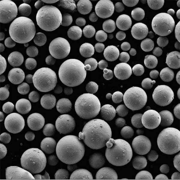
- Primarily used for Ti, Ni, Co alloys, and other high performance materials.
- Provides near-full density parts with properties equaling or exceeding traditionals means.
- Supports complex geometries not feasible by conventional fabrication.
- Commonly used in aerospace, medical, and automotive industries.
- Also referred to as electron beam additive manufacturing (EBAM) or electron beam freeform fabrication (EBF3).
Electron Beam Melting Equipment
| Type | Description |
|---|---|
| Electron beam gun | Generates and focuses high energy beam to melt the material. Key component. |
| Powder bed | Contains powder layers raked by blades or rollers. Built on a movable platform. |
| Vacuum chamber | Entire system is under vacuum during builds. Critical for beam focus. |
| Control system | Software slices and controls build parameters. Provides in-process monitoring and control. |
| Handling system | For loading/unloading parts and recycling unused powder. |
| Shielding | Lead shielding required around chamber due to x-ray generation. |
Materials Used in Electron Beam Melting
| Material | Key Properties | Typical Applications |
|---|---|---|
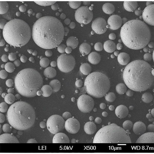
| Titanium alloys | High strength-to-weight ratio, biocompatibility | Aerospace, medical implants |
| Nickel alloys | Corrosion resistance, high strength | Turbines, rocket components |
| Cobalt-chrome alloys | Hardness, wear/corrosion resistance | Medical implants, tooling |
| Stainless steel | Good durability, easier processing | Industrial tooling, molds |
| Aluminum alloys | Low weight | Aerospace, automotive |
| Precious metals | Highly chemically inert | Jewelry, medical |
EBM can process high-performance alloys difficult with laser-based processes due to power intensity.
EBM Process Specifications
| Parameter | Typical Range |
|---|---|
| Beam power | 1-3 kW |
| Beam voltage | 30-150 kV |
| Build size | 200 x 200 x 350 mm max |
| Layer height | 50-200 μm |
| Build speed | 5-100 cm3/hr |
| Beam size | 0.1-1 mm diameter |
| Vacuum level | 5 x 10⁻⁴ mbar |
| Beam focus | 0.1-0.5 mm spot size |
EBM systems allow adjusting parameters like beam power, speed, focus etc. to tune for specific materials.
Suppliers of EBM Systems
| Supplier | Key Details | Starting Price Range |
|---|---|---|
| Supplier 1 | Pioneer of EBM technology. Largest installed base. | $1.2-$1.5 million |
| Supplier 2 | Systems for smaller parts. Faster scan speeds. | $0.8-$1.2 million |
| Supplier 3 | Research systems. Open parameters control. | $0.5-$0.8 million |
System costs vary based on build volume, beam power, included accessories and software capabilities.
How to Choose an EBM System Supplier
| Selection Criteria | Key Considerations | Description |
|---|---|---|
| Supplier Expertise | Industry Knowledge | Does the supplier have a proven track record in your specific industry? Experience with similar applications ensures a deeper understanding of your needs and potential challenges. |
| EBM System Portfolio | What range of EBM systems does the supplier offer? Look for a supplier with a portfolio that caters to your budget, complexity, and desired functionalities. | |
| Customization Capabilities | Can the supplier customize the EBM system to fit your unique requirements? This could involve tailoring data inputs, reports, or integrating with existing software. | |
| Technical Capabilities | Software Features | Evaluate the features offered by the EBM system. Does it provide the functionalities you need for simulation, optimization, and analysis? Consider features like model libraries, scenario planning, and visualization tools. |
| Scalability | Will the EBM system be able to handle your current and future needs? As your business grows, the EBM system should adapt to accommodate more complex models and data volumes. | |
| Integration Capabilities | Can the EBM system integrate seamlessly with your existing software infrastructure? Seamless integration ensures smooth data flow and eliminates the need for manual data entry. | |
| Implementation & Support | Implementation Process | Does the supplier offer a well-defined implementation process? Look for a clear roadmap with defined timelines, milestones, and training sessions. |
| Technical Support | What level of technical support does the supplier offer? Opt for a supplier with responsive and knowledgeable support personnel who can address your technical challenges efficiently. | |
| User Training | Does the supplier provide comprehensive user training? Training empowers your team to leverage the EBM system effectively and maximize its benefits. | |
| Supplier Reputation & Reliability | Financial Stability | Research the supplier’s financial health. A stable company is more likely to provide ongoing support and maintain the EBM system over the long term. |
| Customer References | Request references from existing customers in your industry. Talking to satisfied customers can provide valuable insights into the supplier’s capabilities and service quality. | |
| Industry Recognition | Has the supplier received industry awards or recognition for their EBM systems? Recognition indicates a strong reputation for quality and innovation. | |
| Cost & Value | Licensing Costs | Compare the licensing costs of different EBM systems. Consider the cost in relation to the value the system delivers and its potential return on investment (ROI). |
| Implementation Costs | Factor in the implementation costs, including training and any necessary customization. | |
| Ongoing Support Costs | Understand the costs associated with ongoing technical support and maintenance. |
How to Optimize the EBM Process
| Factor | Description | Impact on Part Quality | Optimization Strategies |
|---|---|---|---|
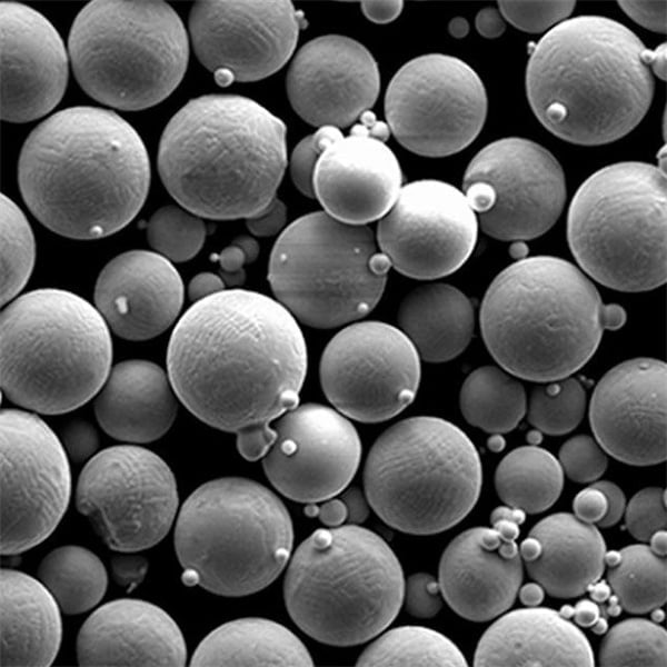
| Powder Material | Particle size, distribution, chemistry | Directly influences melting behavior, density, and mechanical properties | Use spherical powders with a tight size distribution for even packing and flow. Select powder chemistry based on desired final part properties (e.g., strength, corrosion resistance). Implement pre-heating or drying procedures to remove moisture and improve flowability. |
| Beam Parameters | Beam power, scan speed, spot size, scan pattern | Control melt depth, thermal gradients, and residual stress | Fine-tune beam power and scan speed to achieve full melting without excessive spatter or vaporization. Adjust scan patterns (hatch spacing, scan rotation) to minimize heat concentration and warping. Utilize beam offsetting techniques to compensate for shrinkage during melting. |
| Build Environment | Vacuum pressure, chamber temperature | Maintains a clean, controlled atmosphere and reduces oxidation | Maintain high vacuum levels (typically 10^-4 Pa) to prevent gas contamination. Pre-heat the chamber to a temperature slightly below the melting point of the powder to improve flowability and reduce thermal shock. |
| Support Structures | Design, material | Ensure proper heat dissipation and prevent part collapse | Design minimal but sufficient support structures to minimize material usage and post-processing time. Utilize lattice structures or breakaway supports for complex geometries. Explore alternative support materials (e.g., water-soluble supports) to simplify post-processing. |
| Process Monitoring & Control | Melt pool monitoring, layer thickness control | Ensures consistent build quality and identifies potential defects | Implement real-time melt pool monitoring systems (e.g., pyrometry, melt pool imaging) to adjust process parameters for optimal melting behavior. Employ closed-loop feedback systems to automatically adjust layer thickness based on sensor data. |
| Post-Processing Techniques | Hot Isostatic Pressing (HIP), machining, surface finishing | Improve mechanical properties, dimensional accuracy, and surface quality | Utilize HIP to eliminate internal voids and enhance part density. Implement stress relief machining techniques to minimize residual stresses and improve fatigue life. Employ appropriate surface finishing methods (e.g., shot peening, polishing) based on desired surface characteristics. |
How to Design Parts for EBM
| Feature | Description | Benefit for EBM | Considerations |
|---|---|---|---|
| Wall Thickness | The minimum thickness of a solid feature in your design. | Enables intricate details and internal channels. | Too thin (< 0.3mm) can cause poor resolution and cracking. Consider minimum thickness based on material and desired mechanical properties. |
| Overhang Angles | The angle at which a feature juts out without support. | Achieves complex geometries. | Angles steeper than 45° typically require support structures, increasing post-processing and potentially reducing strength. Redesign features with gentler slopes or utilize lattice structures for overhang support. |
| Internal Features | Channels, cavities, and hollow sections within the part. | Lightens weight and creates space for fluid flow or heat dissipation. | Ensure adequate wall thickness for internal features to avoid collapse during printing. Design channels with rounded corners to minimize stress concentration points. Large internal cavities might require strategically placed drainage holes for excess powder removal. |
| Draft Angles | The angle of taper on vertical sidewalls. | Promotes easier powder removal and reduces surface roughness. | Minimum draft of 5-10° is recommended for most metals. Steeper drafts may be needed for complex features or deep cavities. |
| Support Structures | Temporary structures generated by the software to hold up overhanging features. | Enables intricate geometries beyond natural build angles. | Minimize support usage to reduce post-processing time and potential support mark removal issues. Design for self-supporting features whenever possible. When supports are necessary, choose breakaway or dissolvable support types for easier removal. |
| Lattice Structures | Open, cellular structures used internally for weight reduction or customized stiffness. | Optimizes weight-to-strength ratio and achieves specific mechanical properties. | Explore various lattice types (e.g., cubic, diamond) based on desired load-bearing characteristics. Ensure adequate strut thickness within the lattice to maintain structural integrity. |
| Surface Finish | The final texture of the printed part’s surface. | Achieves desired aesthetics or functional requirements. | As-printed EBM surfaces can be slightly rough. For smoother finishes, consider post-processing techniques like machining or polishing. Design features with minimal overhangs to reduce the need for extensive surface finishing. |
| Material Selection | The type of metal powder used for printing. | Leverages unique properties of various metals. | Common EBM materials include titanium alloys, Inconel, and CoCr. Consider factors like strength, corrosion resistance, biocompatibility, and thermal properties when selecting a material. |
| Thermal Management | Strategies to minimize heat-related distortions during printing. | Maintains dimensional accuracy and reduces residual stress. | Utilize wall thickness variations to distribute heat evenly. Design for heat dissipation paths through internal channels or lattice structures. Explore printing strategies like scan path optimization to minimize heat concentration in specific areas. |
How to Post-Process EBM Parts
| Step | Description | Purpose | Techniques | Considerations |
|---|---|---|---|---|
| Depoldering | The first and essential step involves removing unbound metal powder surrounding the built part. | Ensures safe handling, prevents contamination, and allows for proper inspection and subsequent finishing. | Mechanical depowdering: A variety of automated and manual depowdering stations use brushes, compressed air, and vibration to remove loose powder. Water Jetting: A high-pressure water jet carefully removes powder while minimizing surface roughness. | Choose the depowdering method based on part geometry and material properties. For instance, intricate features may require water jetting for gentler removal. Ensure proper ventilation and dust collection during mechanical depowdering. |
| Support Structure Removal | EBM parts often require temporary support structures during printing to prevent overhanging features from collapsing. | Allows for the removal of support structures without damaging the final part. | Wire EDM (Electrical Discharge Machining): A precise method that uses electrical sparking to cut through support structures. Grinding: Manual or CNC-controlled grinding removes larger support structures. Chemical Milling: A chemical bath dissolves support structures made from soluble materials. | Wire EDM offers high accuracy but may be time-consuming for complex supports. Grinding is faster but requires skilled operators to avoid damaging the part. Chemical milling is suitable for large batches of similar parts with soluble supports. |
| Surface Roughness Reduction | The inherent stair-step effect from layer-by-layer printing in EBM results in a rough surface texture. | Improves part aesthetics, functional performance, and tribological properties (wear and friction). | Sanding and Abrasive Tumbling: Abrasive media smoothens surfaces through friction. Vibratory Finishing: Parts are vibrated in a media bed for overall surface improvement. Polishing: Mechanical or electrochemical polishing creates a mirror-like finish. | The chosen technique depends on the desired surface finish and geometry. Sanding is effective for flat surfaces, while tumbling works well for complex shapes. Polishing achieves the smoothest finish but may alter dimensions. |
| Stress Relief | The rapid heating and cooling during EBM can introduce residual stresses in the part. | Reduces the risk of warping, cracking, and improves dimensional stability. | Thermal Annealing: The part is heated to a specific temperature and held for a controlled time to allow stresses to relax. | Annealing parameters depend on the material and part geometry. Improper annealing can adversely affect mechanical properties. Consultation with material experts is recommended. |
| Inspection and Quality Control | The final step ensures the finished part meets dimensional tolerances, surface finish requirements, and is free of cracks or defects. | Verifies part conformity to design specifications and ensures functionality. | Dimensional Measurement: Coordinate measuring machines (CMMs) measure part features with high precision. Surface Roughness Measurement: Profilometers quantify the surface texture. Non-Destructive Testing (NDT): Techniques like X-ray radiography and ultrasonic testing detect internal cracks and defects. | The inspection plan should be established prior to printing based |
How to Install and Integrate EBM Parts
| Step | Task | Description | Considerations |
|---|---|---|---|
| 1 | Preparation | Before diving into installation, ensure a smooth integration process. | Identify EBM Parts: Clearly define the Evidence-Based Medicine (EBM) components you intend to integrate. Are they clinical decision support tools, standardized protocols, or patient education materials? System Compatibility: Verify compatibility between the EBM parts and your existing electronic health record (EHR) system or platform. Different systems may require specific file formats or integration methods. Data Mapping: Plan how data from the EBM parts will be mapped to corresponding fields within your EHR system. This ensures seamless information flow and avoids data redundancy. Workflow Analysis: Analyze your current workflows to identify the most suitable points for EBM part integration. This minimizes disruption and optimizes user adoption. |
| 2 | Installation | Follow the specific instructions provided by the EBM part vendor. | Technical Expertise: Depending on the complexity of the EBM parts, you might require assistance from your IT team or the EBM part vendor for installation. System Downtime: Schedule installation during non-peak hours to minimize disruption to ongoing clinical activities. Testing: Conduct thorough testing after installation to ensure the EBM parts function correctly and integrate seamlessly with your EHR system. Test various scenarios to identify and address any potential issues. |
| 3 | Configuration | Tailor the EBM parts to your specific needs and workflows. | User Roles and Permissions: Define user roles and assign appropriate permissions for accessing and utilizing the EBM parts within your system. Customization Options: Explore customization options offered by the EBM parts. This might involve tailoring decision support prompts, alert thresholds, or educational content to better suit your patient population and clinical practice. Reporting and Analytics: Configure reporting features to track the usage and impact of the EBM parts. This data can be valuable for evaluating effectiveness and identifying areas for further optimization. |
| 4 | Training and Support | Equip your staff with the knowledge and skills to effectively utilize the EBM parts. | User Training: Develop training materials and conduct sessions for clinicians and staff to familiarize them with the functionalities, benefits, and limitations of the EBM parts. Ongoing Support: Establish clear channels for ongoing support from the EBM part vendor or your IT team. This ensures users can readily access assistance when encountering difficulties. |
| 5 | Monitoring and Evaluation | Continuously assess the effectiveness of the EBM parts and identify opportunities for improvement. | Performance Monitoring: Track key metrics such as EBM part utilization rates, adherence to protocols, and patient outcomes. User Feedback: Gather feedback from clinicians and staff regarding their experience with the EBM parts. This can reveal areas for improvement or highlight unexpected benefits. Data Analysis: Regularly analyze the data collected during monitoring to identify trends and assess the impact of EBM parts on clinical practice and patient care. |
Operating and Maintaining EBM Printers
| Task | Description | Frequency | Resources |
|---|---|---|---|
| Loading Media | Ensure the correct media type (labels, tags, ribbons) is loaded according to printer specifications. Align media properly in the feeder tray, ensuring it feeds straight and tension is appropriate. Adjust media guides for optimal fit. | Before each print job | Printer manual, Media specifications |
| Ribbon Management | Inspect ribbon for wear and tear. Replace when wrinkled, frayed, or nearing its end. Ensure ribbon type (wax, resin, etc.) matches media and printing requirements. | Before each print job or when print quality deteriorates | Ribbon specifications, Printer manual |
| Print Job Submission | Verify print settings (resolution, quantity, media size, orientation) match document specifications. Select the appropriate printer driver on the computer. Preview the print job to ensure accuracy before sending it to the printer. | Each print job | Printer software, Document creation software |
| Monitoring Print Status | Observe printer notifications for errors or warnings (low media, ribbon issues, print head problems). Regularly check the printer output for quality issues (streaks, smudges, misalignment). | During printing | Printer display panel, Printed output |
| Daily Cleaning | Use a lint-free cloth to wipe exterior surfaces of the printer. Clean the print head with a cotton swab dampened with isopropyl alcohol (consult manual for specific instructions). | Daily | Lint-free cloth, Isopropyl alcohol (recommended concentration in manual), Printer manual |
| Scheduled Maintenance | Follow manufacturer’s recommendations for periodic cleaning of the print path (rollers, platen). Replace worn-out print head or other components as needed, following the printer manual’s instructions. | Every 3-6 months (or as directed by the manual) | Printer manual, Replacement parts (consult manual for compatibility) |
| Troubleshooting | Refer to the printer manual’s troubleshooting guide for common issues (paper jams, printing errors). Contact EBM technical support for assistance with complex problems. | As needed | Printer manual, EBM technical support contact information (phone number, website) |
Pros and Cons of Electron Beam Melting
| Feature | Pros | Cons |
|---|---|---|
| Part Quality | High Density: EBM creates parts with near-net density (>99.5%) due to the powerful electron beam completely melting the metal powder. This translates to strong, functional parts with excellent mechanical properties comparable to wrought metals. Complex Geometries: EBM excels at producing intricate features and internal channels due to the precise control of the electron beam. Unlike some other additive manufacturing processes, there’s no need for support structures for overhanging features. | Surface Finish: The layer-by-layer melting process in EBM results in a slightly rougher surface finish compared to techniques like Selective Laser Melting (SLM). This might necessitate post-processing for applications requiring a smooth aesthetic. Accuracy: While highly precise, EBM’s electron beam diameter is inherently larger than the laser beam used in SLM. This can lead to slightly less precise dimensional tolerances compared to SLM-printed parts. |
| Material Compatibility | Broad Range of Metals: EBM boasts exceptional compatibility with a wide variety of reactive and refractory metals, including titanium alloys, Inconel, and even some rare earth metals. This makes it ideal for applications where these high-performance materials are crucial. | Powder Handling: Reactive metals used in EBM are highly susceptible to oxidation and contamination. The entire EBM process needs to occur in a vacuum environment to prevent these issues, adding complexity and cost. |
| Speed and Efficiency | Faster Build Times: The high energy density of the electron beam allows for faster melting and quicker build times compared to SLM, especially for larger parts. Material Reuse: Unused metal powder in the EBM chamber can be recycled and reused to a high degree, minimizing waste and material costs. | Layer-by-Layer Process: Despite faster melting, EBM’s inherent layer-by-layer nature can still lead to longer build times compared to additive methods that deposit entire layers at once. |
| Operational Considerations | Vacuum Environment: The need for a high vacuum environment in the EBM chamber adds complexity to the system and necessitates specialized training for operators. Safety: EBM processes generate X-rays due to the high-energy electron beam. Proper safety protocols and equipment are essential to protect operators. | Cost: EBM machines and their operation tend to be more expensive compared to some other additive manufacturing technologies. This can be a barrier for entry, particularly for smaller companies. |
FAQ
Q: What materials can you process with EBM?
A: Primarily titanium, nickel, cobalt, and stainless steel alloys to date. Research is expanding material options including aluminum, tool steels, gold, tantalum, and more.
Q: What is the main difference between EBM and selective laser melting (SLM)?
A: EBM uses an electron beam energy source whereas SLM uses a laser. The higher beam power densities achievable with EBM allow processing of more refractory metals.
Q: What industries use EBM printing?
A: Aerospace is the largest adopter to date for components like turbine blades. But medical, automotive, and industrial sectors are also growing users of EBM.
Q: Does EBM produce porous or fully dense parts?
A: EBM can attain over 99% density with optimal parameters. The high temperature builds improve diffusion bonding between layers.
Q: What size parts can you create with EBM?
A: The maximum size is restricted by the build envelope, typically around 250 x 250 x 300 mm. Larger systems are in development targeting 500 mm cubes.
Q: How accurate is EBM compared to CNC machining?
A: EBM can achieve tolerances down to 0.1-0.3 mm when well calibrated. But machining is needed to reach tighter tolerances below 0.05 mm.
Q: What are some key benefits of EBM?
A: Design freedom, part consolidation, rapid prototyping, high strength alloys, reduced waste, and short lead times versus traditional fabrication.
Q: What safety precautions are required for EBM?
A: EBM systems generate x-ray radiation so adequate lead shielding of the build chamber is critical. Only trained personnel should operate.
Share On
MET3DP Technology Co., LTD is a leading provider of additive manufacturing solutions headquartered in Qingdao, China. Our company specializes in 3D printing equipment and high-performance metal powders for industrial applications.
Inquiry to get best price and customized Solution for your business!
Related Articles
About Met3DP
Recent Update
Our Product
CONTACT US
Any questions? Send us message now! We’ll serve your request with a whole team after receiving your message.

Metal Powders for 3D Printing and Additive Manufacturing
COMPANY
PRODUCT
cONTACT INFO
- Qingdao City, Shandong, China
- [email protected]
- [email protected]
- +86 19116340731


