SLM for Metal Additive Manufacturing
Table of Contents
Overview of Selective Laser Melting
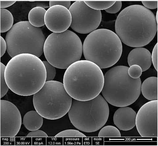
Selective laser melting (SLM) is a powder bed fusion metal 3D printing process that uses a laser to selectively melt and fuse metallic powder particles layer-by-layer to build up fully dense parts.
Key attributes of SLM technology:
| Characteristic | Description |
|---|---|
| Materials | Metals like stainless steel, titanium, aluminum, nickel alloys |
| Laser type | Fiber, CO2, or direct diode lasers |
| Atmosphere | Inert argon or nitrogen atmosphere |
| Resolution | Capable of fine features down to 150 μm |
| Accuracy | Parts within ±0.2% dimensions or better |
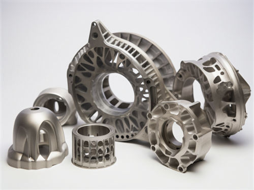
SLM enables complex, customizable metal parts for aerospace, medical, automotive, and industrial applications.
How Selective Laser Melting Works
The SLM printing process works as follows:
- 3D model sliced into 2D cross-section layers
- Powder spread over build plate in thin layer
- Laser selectively scans layer, melting powder
- Melted powder solidifies and fuses together
- Build plate lowers and new layer spread on top
- Process repeats until full part built up
The unfused powder provides support while building up the component. This enables complex geometries without dedicated support structures.

Types of Selective Laser Melting Systems
There are several SLM system configurations:
| System | Details |
|---|---|
| Single laser | One high power laser for melting |
| Multi laser | Multiple lasers to increase build speed |
| Scanning system | Galvo mirrors or fixed optics |
| Metal powder handling | Open systems or closed powder recycling |
| Atmosphere control | Sealed build chamber filled with argon or nitrogen |
Multi-laser systems offer faster builds while closed-loop powder handling improves efficiency and recyclability.
Materials for Selective Laser Melting
Common metal materials used for SLM include:
| Material | Benefits |
|---|---|
| Aluminum alloys | Lightweight with good strength |
| Titanium alloys | High strength-to-weight ratio |
| Stainless steels | Corrosion resistance, high toughness |
| Tool steels | High hardness and wear resistance |
| Nickel alloys | High temperature resistance |
| Cobalt-Chrome | Biocompatible with good wear |
A range of alloy powders enables properties like strength, hardness, temperature resistance, and biocompatibility needed across applications.
Applications of Selective Laser Melting
Typical applications of SLM metal printing include:
| Industry | Applications |
|---|---|
| Aerospace | Engine components, lightweight structures |
| Medical | Custom implants, prosthetics, instruments |
| Automotive | Lightweight parts, custom tooling |
| Industrial | Lightweighting components, end-use production |
| Oil and gas | Corrosion resistant valves, wellhead parts |
SLM enables complex, custom metal parts consolidated into one piece and optimized for weight and performance.
Benefits of Selective Laser Melting
Key advantages of SLM technology:
| Benefit | Description |
|---|---|
| Complex geometries | Unlimited design freedom for organic shapes |
| Part consolidation | Assemblies printed as one single component |
| Customization | Easily adapted to produce custom parts |
| Lightweighting | Lattice structures and topology optimization |
| Material savings | Reduced waste compared to subtractive methods |
| Post-processing | May require support removal and surface finishing |
These advantages enable higher performing end-use metal parts at competitive lead times and costs at lower production volumes.

Limitations of Selective Laser Melting
Limitations of SLM include:
| Limitation | Description |
|---|---|
| Part size | Restricted to printer build volume, typically under 1 m3 |
| Productivity | Relatively slow production rates limit high volumes |
| Post-processing | May require support removal, machining, finishing |
| Anisotropy | Mechanical properties vary depending on build orientation |
| Surface finish | As-printed surface is relatively rough |
| Operator expertise | Requires extensive printer experience |
The technology is best suited for low to medium production volumes of complex metal parts.
SLM Printer Suppliers
Leading SLM system manufacturers:
| Company | Notable Systems |
|---|---|
| EOS | EOS M series |
| 3D Systems | DMP series |
| GE Additive | X Line 2000R |
| Trumpf | TruPrint 1000, 3000 |
| SLM Solutions | SLM 500, SLM 800 |
| Renishaw | AM500, AM400 |
Machines range from smaller build volumes around 250 x 250 x 300 mm up to large 800 x 400 x 500 mm systems for high productivity.
Selecting an SLM 3D Printer
Key considerations when selecting an SLM system:
| Factor | Priority |
|---|---|
| Build volume | Match to required part sizes |
| Supported materials | Needed alloys like Ti, Al, stainless, tool steels |
| Inert gas system | Sealed, automated argon or nitrogen handling |
| Laser technology | Fiber, CO2, or direct diode lasers |
| Scanning method | Galvo or fixed mirror scanning |
| Powder handling | Closed-loop recycling preferred |
The optimum SLM system provides the materials, build volume, speed, and powder handling features required for the applications.
SLM Facility Requirements
To operate an SLM printer, the facility must meet:
- Electrical power levels 20-60 kW typical
- Stable temperature around 20-25°C
- Low humidity below 70% RH
- Particulate control and metal powder handling
- Inert gas supply and venting
- Exhaust filtration for released particulates
- Monitoring systems for atmosphere
- Strong personnel safety procedures
SLM systems require substantial infrastructure for power, cooling, powder handling, and inert gas delivery.
SLM Printing Process Parameters
Typical SLM printing parameters:
| Parameter | Typical Range |
|---|---|
| Laser power | 100-400 W |
| Scanning speed | 100-2000 mm/s |
| Layer thickness | 20-100 μm |
| Hatch spacing | 50-200 μm |
| Spot size | 50-100 μm |
| Scanning pattern | Alternating, rotated for each layer |
Precise adjustment of these parameters is required to achieve fully dense parts for each alloy powder.
SLM Design Guidelines and Limitations
Key SLM design guidelines include:
| Guideline | Reason |
|---|---|
| Minimum wall thickness | Avoid heat buildup and warping |
| Supported overhangs | Prevent collapse without supports |
| Avoid thin features | Prevent melting or vaporization |
| Orient for strength | Optimize for load direction |
| Minimize support use | Simplify post-processing |
The SLM process imposes geometric requirements like overhang angles and minimum feature sizes that must be accounted for.
SLM Post-Processing Requirements
Common post-processing steps for SLM parts:
| Process | Purpose |
|---|---|
| Support removal | Remove auto-generated supports from software |
| Powder removal | Clean remaining powder from internal passages |
| Surface finishing | Improve surface finish and roughness through machining |
| Stress relieving | Reduce residual stresses through heat treatment |
| Hot isostatic pressing | Improve density and reduce internal voids |
The level of post-processing depends on the application requirements for tolerances, surface finishes, and material properties.
Qualification Testing for SLM Parts
Typical qualification tests for SLM components:
| Test Type | Description |
|---|---|
| Density analysis | Measure density compared to wrought materials |
| Mechanical testing | Tensile, fatigue, fracture toughness tests |
| Metallography | Microstructure imaging and defect analysis |
| Chemical analysis | Check composition matches specification |
| Non-destructive | CT scanning or X-ray inspection for voids |
Thorough testing ensures SLM parts meet requirements before being put into production applications.
Benefits of SLM Technology
Selective laser melting provides key advantages:
- Complex, organic geometries not possible with casting or CNC
- lighter weight structures through topology optimization
- Part consolidation into single printed components
- Reduced waste compared to subtractive methods
- Customization and rapid design iterations
- Just-in-time production of metal parts
- High strength and hardness approaching wrought materials
These benefits make SLM suitable for producing high value, low volume parts on-demand across industries.
Challenges of Adopting SLM Printing
Barriers to adoption of SLM include:
| Challenge | Mitigation Strategies |
|---|---|
| High printer cost | Leverage service bureaus, validate ROI |
| Material options | New alloys in development, specialty suppliers |
| Process knowledge | Training programs, learning curve |
| Standards | Part qualification protocols being developed |
| Post-processing | Automated processes under development |
As the technology matures, these barriers are being reduced through improved materials, equipment, training, and standardization efforts across the industry.
The Future of Selective Laser Melting
Emerging trends in SLM technology:
- Larger build volumes above 500 x 500 x 500 mm
- Multi-laser systems for faster build rates
- Expanded alloys including high-temperature superalloys
- Improved powder recyclability and handling
- Automated support removal and post-processing
- Hybrid manufacturing combining AM and CNC
- Specialized software for design optimization
- Standardization of process parameters and part qualification
SLM systems will continue advancing in terms of build size, speed, materials, and reliability to meet production needs across more industrial applications.

Summary of Key Points
- SLM selectively fuses metal powder with a laser for full density 3D printing
- Powder bed fusion process capable of fine details and complex geometries
- Suitable for aerospace, medical, automotive, and industrial applications
- Uses metals like stainless steel, titanium, aluminum, and nickel alloys
- Provides benefits of part consolidation, customization, lightweighting
- Requires controlled atmosphere and robust powder handling systems
- Significant post-processing may be needed on printed parts
- Leading technology for low to medium volume production applications
- Ongoing improvements in materials, build size, speed, and quality
- Enables high performance printed metal components
Selective laser melting will continue growing as an industrial manufacturing solution for customized metal parts on-demand.
FAQ
| Question | Answer |
|---|---|
| What materials are compatible with SLM? | Most weldable alloys like stainless steel, titanium, aluminum, tool steel, nickel alloys, and cobalt-chrome. |
| What is the typical accuracy of SLM parts? | Dimensional accuracy around ±0.2% is achievable for most geometries. |
| What post-processing is required? | Support removal, powder removal, surface finishing, stress relieving, and hot isostatic pressing are common. |
| What are common SLM defects? | Porosity, cracking, layer delamination, warp, poor surface finish, unmelted particles. |
| What types of lasers are used in SLM? | Fiber lasers, CO2 lasers, or high-power diodes are commonly used. |
Share On
MET3DP Technology Co., LTD is a leading provider of additive manufacturing solutions headquartered in Qingdao, China. Our company specializes in 3D printing equipment and high-performance metal powders for industrial applications.
Inquiry to get best price and customized Solution for your business!
Related Articles
About Met3DP
Recent Update
Our Product
CONTACT US
Any questions? Send us message now! We’ll serve your request with a whole team after receiving your message.

Metal Powders for 3D Printing and Additive Manufacturing
COMPANY
PRODUCT
cONTACT INFO
- Qingdao City, Shandong, China
- [email protected]
- [email protected]
- +86 19116340731


