3D Printing Metal Powder in 2025
Table of Contents
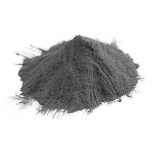
3D printing metal powder is revolutionizing manufacturing across industries like aerospace, medical, and automotive. This advanced additive manufacturing technology allows complex metal parts to be created directly from 3D CAD data by selectively melting layers of fine metallic powder.
This comprehensive guide will examine all aspects of metal powder 3D printing to help you understand the technology and applications.
Overview of 3D Printing Metal powder
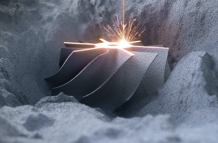
Metal 3D printing, also known as direct metal laser sintering (DMLS) or selective laser melting (SLM), is an additive manufacturing process that uses a high-powered laser to fuse fine metallic powder into solid 3D objects.
A 3D printer builds up metal parts layer-by-layer from powdered metal materials like aluminum, titanium, nickel alloys, and stainless steel. The technology offers unparalleled design freedom and impressive material properties unmatched by traditional manufacturing.
Key Details About 3D Printing Metal Powder:
| Parameter | Details |
|---|---|
| Technology | Powder bed fusion process using laser to selectively melt metallic powder |
| Materials | Aluminum, titanium, nickel, stainless steel, cobalt-chrome, precious metals |
| Hardware | 3D printer with high power laser, powder bed, rake system |
| Process | Spread thin layer of powder, selectively melt with laser, add layers to build parts |
| Properties | High strength, evenly distributed material, complex internal geometry |
| Applications | Aerospace, medical implants, automotive, tooling, jewelry |
| Benefits | Design freedom, weight reduction, part consolidation, rapid prototyping |
| Limitations | High equipment cost, limited size, post-processing required |
This additive manufacturing method delivers numerous benefits over traditional subtractive techniques like CNC machining such as increased design freedom, part consolidation, rapid prototyping, and significant weight reduction. The ability to 3D print complex metal components is enabling key innovations across industries.
Types of 3D Printing Metal Powder
3D printing metal powders are essential materials in additive manufacturing, offering unique properties for various industries like aerospace, automotive, medical, and energy. Below is an overview of the major categories of 3D printing metal powders and their common types, presented in a table format for clarity.
Related Products
1. Titanium Alloys
Titanium powders are lightweight, strong, and corrosion-resistant, making them ideal for aerospace and medical applications.
| Type | Description | Applications |
|---|---|---|
| Ti6Al4V (Grade 5) | High strength-to-weight ratio, widely used titanium alloy. | Aerospace, automotive, medical implants |
| Ti6Al4V ELI | Purified version of Grade 5, extra-low interstitials for biocompatibility. | Medical implants, prosthetics |
| Pure Titanium | Grades 1-4, excellent corrosion resistance and biocompatibility. | Chemical processing, medical implants |
2. Stainless Steels
Stainless steel powders are durable, corrosion-resistant, and widely used for structural and functional parts.
| Type | Description | Applications |
|---|---|---|
| 316L Stainless Steel | Excellent corrosion resistance and mechanical properties. | Medical tools, food processing, marine |
| 17-4PH Stainless Steel | Precipitation-hardened steel with high strength and wear resistance. | Aerospace, automotive, industrial tools |
| 304 Stainless Steel | Cost-effective, moderate corrosion resistance. | Consumer goods, structural components |
3. Aluminum Alloys
Aluminum powders are lightweight and have excellent thermal conductivity, ideal for aerospace and automotive uses.
| Type | Description | Applications |
|---|---|---|
| AlSi10Mg | Good mechanical properties and heat resistance. | Aerospace, automotive, industrial parts |
| AlSi12 | High thermal conductivity, good wear resistance. | Heat exchangers, lightweight parts |
| Aluminum 7075 | High strength and low weight, suitable for heavy-duty applications. | Aerospace, structural components |
4. Nickel-Based Alloys
Nickel alloys excel in extreme environments, offering high-temperature and corrosion resistance.
| Type | Description | Applications |
|---|---|---|
| Inconel 718 | High strength and oxidation resistance, suitable for extreme conditions. | Turbine blades, jet engines, energy sector |
| Inconel 625 | Exceptional resistance to harsh environments, including marine. | Marine, chemical processing |
| Hastelloy X | Outstanding heat and chemical resistance. | Aerospace, high-temperature environments |
5. Cobalt-Chromium Alloys
Cobalt-chromium powders are highly wear-resistant and biocompatible, perfect for medical and dental applications.
| Type | Description | Applications |
|---|---|---|
| CoCrMo | Combines strength, wear resistance, and biocompatibility. | Dental implants, orthopedic devices |
| CoCrW | High hardness and heat resistance, suitable for demanding applications. | Turbine blades, high-wear parts |
6. Tool Steels
Tool steels are known for their hardness and wear resistance, commonly used in manufacturing tools and molds.
| Type | Description | Applications |
|---|---|---|
| H13 Tool Steel | Heat-resistant steel, ideal for tooling and molds. | Injection molding, die casting |
| Maraging Steel | Excellent strength and toughness, suitable for high-stress parts. | Aerospace, tooling |
7. Precious Metals
Precious metals are used in luxury goods, jewelry, and electronics for their aesthetic and conductive properties.
| Type | Description | Applications |
|---|---|---|
| Gold (Au) | High value and corrosion resistance, used in decorative applications. | Jewelry, electronics |
| Silver (Ag) | Exceptional thermal and electrical conductivity. | Electronics, conductive components |
| Platinum (Pt) | High durability and resistance, used in high-end applications. | Jewelry, catalytic converters |
8. Copper Alloys
Copper-based powders offer outstanding thermal and electrical conductivity for specialized applications.
| Type | Description | Applications |
|---|---|---|
| Pure Copper | Excellent conductivity, suitable for electrical applications. | Electronics, heat exchangers |
| Copper Alloys | Enhanced mechanical properties with good conductivity (e.g., CuCrZr). | Electrical components, tooling |
3D Printing metal powder Processes
There are several similar powder bed fusion technologies used for metal 3D printing:
Metal Powder Bed Fusion Processes
| Process | Details |
|---|---|
| Direct Metal Laser Sintering (DMLS) | Uses laser to selectively fuse metallic powder in an inert gas atmosphere |
| Selective Laser Melting (SLM) | Very similar to DMLS, melts powder fully into solid parts |
| Electron Beam Melting (EBM) | Uses electron beam instead of laser for higher build rates |
| Selective Laser Sintering (SLS) | Sinters powder together into a solid part without fully melting |
| Direct Metal Laser Melting (DMLM) | Another term for DMLS process |
| LaserCUSING | Process developed by Concept Laser |
| LASFORM | Process by DMG MORI |
The most common technologies used are DMLS and SLM. Both use a high powered ytterbium fiber laser to fully melt and fuse the metallic powder in order to grow 3D objects from CAD data.
The main difference between SLM and DMLS is that SLM aims to achieve full melting and dense parts, while DMLS may produce parts with some porosity between powder particles. However, the terms are often used interchangeably.
Electron beam melting (EBM) uses an electron beam heat source rather than a laser, allowing faster build speeds. But EBM can only be used with conductive materials like titanium and nickel alloys.
Selective laser sintering (SLS) uses lower temperatures to fuse the powder into solid parts without reaching full melting point. This produces more porous metal parts.
Metal Materials for Powder Bed 3D Printing
A range of metals and alloys can be processed into fine powders for use in powder bed fusion 3D printing technologies:
Metals for Powder Bed 3D Printing
| Material | Details | Applications |
|---|---|---|
| Titanium | High strength-to-weight ratio, biocompatible | Aerospace, medical implants |
| Aluminum | Lightweight, high strength | Automotive, aerospace |
| Nickel Alloys | Corrosion resistance, high strength | Aerospace, marine |
| Stainless Steel | Corrosion resistance, high hardness | Industrial tooling, molds |
| Cobalt-Chrome | Biocompatible, wears well | Dental, medical implants |
| Precious Metals | Jewelry, durability | Jewelry, luxury goods |
| Tool Steels | Heat resistance, hardness | Metal forming, injection molds |
| Alloy Steels | High strength, impact resistance | Industrial wear parts |
The most widely used metals are titanium alloys and aluminum due to their high strength-to-weight ratios. Inert nickel alloys like Inconel are popular in aerospace applications. Stainless steel and tool steel powders create durable metal parts with excellent hardness and wear resistance.
Precious metals like gold, silver and platinum allow direct 3D printing of jewelry and luxury items. Custom medical implants often use biocompatible alloys like titanium or cobalt-chrome.
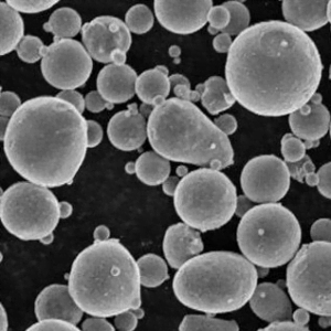
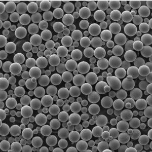
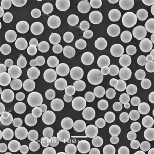
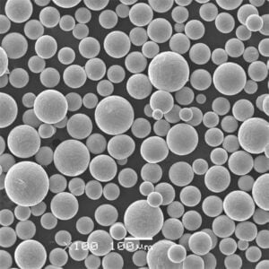
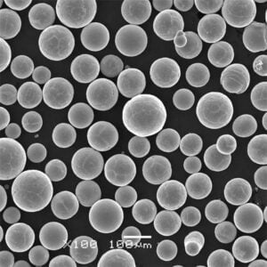
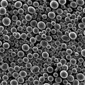
Metal powders for AM are produced by gas or water atomization into precise particle sizes optimally sized for powder bed printing resolution.
Applications of Metal Powder Bed 3D Printing
Metal additive manufacturing enables production of complex, lightweight parts across aerospace, medical, dental, automotive, and industrial sectors.
Industry Applications of Metal Powder Bed 3D Printing:
| Industry | Applications | Benefits |
|---|---|---|
| Aerospace | Aircraft components, turbines, rocket parts | Weight reduction, optimized geometry |
| Medical | Orthopedic implants, surgical instruments | Biocompatible, personalized |
| Automotive | Lightweight parts, custom tooling | Faster development, consolidation |
| Industrial | Injection molds, jigs, fixtures | Optimized conformal cooling |
| Jewelry | Rings, pendants, watches | Unique geometries, gold/silver |
| Dental | Crowns, bridges, aligners | Custom fit, fast production |
In aerospace, metal AM is being used to manufacture lighter aircraft structural components like titanium brackets and stainless steel landing gear parts with optimized strength-to-weight characteristics.
The technology is ideal for customized medical implants like hip joints that match patient anatomy and distribute loads better. Metal printing streamlines automotive manufacturing through part consolidation and lightweight optimized designs.
For industries like injection molding, 3D printed conformal cooling channels in tooling boosts productivity significantly. Jewelers leverage the process for one-of-a-kind jewelry creations in noble metals.
Advantages of Metal Powder Bed 3D Printing
From prototypes to end-use production parts, metal AM offers significant advantages over conventional fabrication processes like machining or metal casting:
Key Benefits of Metal Powder Bed 3D Printing
- Design freedom – Create complex organic shapes and internal lattices impossible with subtractive methods
- Faster process – Additive process with no tooling, low waste – go directly from CAD to metal part
- Weight reduction – Optimize topology for lighter, stronger metal components
- Part consolidation – Combine assemblies into single 3D printed part to reduce manufacturing steps
- Rapid prototyping – Test metal part designs quickly during development
- Customized parts – Easily customize medical implants and other metal parts
- High strength – As-printed metal parts rival traditionals methods like casting
- Reduce inventory – Print on-demand metal spare parts, no pre-production
- Waste reduction – Additive process has material waste rates under 5%
The optimized characteristics of metal AM parts like conformal cooling channels in molds or complex lattice structures in implants are impossible to produce through milling or casting processes.
3D printing complex or customized metal parts straight from CAD data also minimizes production steps relative to subtractive methods that require extensive tooling, machining, and assembly. There is tremendous time and cost savings, making it ideal for low volume production.
Limitations and Challenges of Metal Powder Bed Printing
Despite many benefits, there are some limitations to be aware of when adopting metal powder bed 3D printing:
Limitations of Metal Powder Bed 3D Printing
- High machine cost – Metal 3D printers start around $100,000. Large systems exceed $1M
- Part size limited – Build volumes under 500mm x 500mm x 500mm currently
- Post-processing – Additional labor for supports removal, surface finishing
- Anisotropic material – Mechanical properties vary depending on build orientation
- Standards needed – For aerospace and medical, lacking powder and process standards
- Limited material options – Fewer alloys available than casting or MIM powder metallurgy
- Porosity issues – Process can create small internal voids, depending on parameters
- Unused powder management – Metallic powder handling, recycling requirements
The printer cost and build size constraints may restrict metal AM adoption to relatively low production volumes. Support structures and build plate overhangs also require post-processing like machining.
There is onging development of industry standards for materials, processes, and powder handling as adoption spreads into highly regulated sectors. Currently only a subset of metal alloys are available as optimized pre-alloyed powders for AM.
Anisotropic material properties, where strength varies across X/Y versus Z build directions, require design and process compensation. Internal voids or porosity issues also must be mitigated through dialing in ideal processing parameters.
Metal Powder Bed 3D Printing Process
The powder bed fusion 3D printing process for metals involves spreading thin layers of metal powder and selectively melting it to build up parts:
Metal Powder Bed Fusion 3D Printing Process:
| Step | Description |
|---|---|
| 1. 3D Model | CAD model is 3D sliced into layers |
| 2. Spread Powder | Machine spreads thin layer (~20-100μm) of metallic powder |
| 3. Laser Melting | High power laser selectively fuses powder to melt the layer |
| 4. Lower Bed | Build plate lowers, new layer of powder spread on top |
| 5. Repeat Steps | Steps 2-4 repeated until full part is built up |
| 6. Remove Part | Unfused powder supports part, then removed |
| 7. Post Process | Additional cleaning and surface finishing |
The process starts with a 3D CAD model, usually in STL format, which is processed by a slicer software. This slices the model into layers, essentially creating 2D profiles for each layer, and generates build instructions for the printer.
The printer spreads a thin layer of metallic powder across the powder bed using a wiper system. The laser beam then traces over the layer, melting the metal powder selectively according to that layer’s profile.
The high power laser completely fuses metal particles together into a solidified layer. The build plate then lowers, allowing the next layer of fresh powder to be spread across the previous layer, and the process repeats until the full 3D object is built up from the bottom up.
Any unsintered powder acts as support during the build. After printing, this is simply brushed away to reveal the completed metal part. Often some machining or surface finishing follows to smooth the 3D printed surfaces.
Powder Bed Fusion Printer Hardware
Specialist metal 3D printing systems use powder bed fusion technology to process metal powders. The core components include:
Powder Bed Fusion Printer Components:
| Component | Description |
|---|---|
| Laser system | High power fiber laser ~100-400W for melting metallic powder |
| Powder bed | Metal powder spread in thin layers across this movable bed |
| Powder dispenser | Doses and spreads powder smoothly across bed |
| Powder collection | Collects excess powder to reuse |
| Inert gas flow | Sealed chamber filled with argon or nitrogen |
| Build plate | Lowers as layers are printed on top |
| Optics system | Focuses and steers laser beam over powder bed |
| Control system | Controls laser, optics, powder bed in coordination |
A high powered ytterbium fiber laser is needed to fully melt and fuse the metallic powders into dense parts. The laser energy density and focus must be tightly controlled to achieve ideal melt pools and bonding.
The laser focuses down to around 10s of microns onto the powder bed to trace out the geometry of each successive layer. Galvo mirror optics steer the laser accurately across the bed.
The metal powder is dosed from cartridges by a rake system and spread uniformly across the printing area at around 20-100 microns thickness. Powder is dispensed from the front of the system and excess is collected at the back.
An inert gas like argon or nitrogen fills the build chamber to prevent oxidation of reactive metals like aluminum or titanium. The entire system is controlled by specialized software that integrates the laser, powder bed, and other actuators.
Powder Bed Fusion Process Parameters
Optimizing the various process parameters involved in powder bed fusion is critical to producing high quality metal parts:
Key Powder Bed Fusion Process Parameters:
| Parameter | Typical Range | Effect on Part Quality |
|---|---|---|
| Laser power | 100-400W | Influences melt pool size, controls bonding |
| Beam size | ~50-100μm | Focus spot size affects resolution, precision |
| Scan speed | Up to 10,000 mm/s | Faster scanning affects thermal gradients |
| Hatch spacing | ~50-200μm | Distance between scan tracks, densification |
| Layer height | 20-100μm | Thinner layers improve resolution, surface finish |
| Powder layer | 20-50μm | Uniformity and thickness of powder layer |
| Build plate temp | 60-200°C | Preheating reduces stresses and curling |
Laser power must be high enough (typically 100W to 400W) to fully melt the metallic powder particles together into a solid part. But too much power can create keyholing effects.
Faster scanning of the laser increases production speeds but can create more residual stresses and material anisotropy. The hatch spacing sets the distance between adjacent scan tracks.
Thinner powder layers around 20-50 microns improve resolution, fine details, and surface finish. Preheating the build plate also helps reduce stresses.
Parameter optimization is specific to the powder material, laser optics, inert gas flow and other interdependent factors. Fine tuning is needed to dial in ideal settings.
Post-Processing Steps for Metal AM Parts
After printing complexes metal parts using powder bed fusion, additional post-processing is typically required:
Common Post-Processing Steps for Metal AM Parts:
- Support removal – Remove unsintered powder supports using vibrations, blasting, etc.
- Thermal stress relief – Anneal parts to relieve internal stresses from process
- Surface machining – Traditional methods to smooth surfaces like milling, turning, grinding
- Hot isostatic pressing – Applies high heat and pressure to improve material densities
- Heat treatments – Modify microstructure using controlled heating and cooling cycles
- Surface finishing – Apply coatings, polish finishes for desired surface properties
Support powder is carefully removed using a combination of vibration, blasting with beads or air, and vacuum suction. This powder can often be sieved and reused.
Annealing heat treatments help relieve stresses induced by the intense localized heating during laser melting. Additional surface machining improves dimensional accuracy and surface finish.
Some applications benefit from hot isostatic pressing to further densify parts by applying high uniform gas pressure at elevated temperatures. This minimizes any porosity in as-printed parts.
Desired material microstructures and properties can be achieved through solutionizing, aging, or other heat treatments tailored for the alloy. Additional surface finishing steps like polishing and coatings provide required surface characteristics.
Industrial Metal Powders for Additive Manufacturing
Specialized metal powders have been developed to provide ideal characteristics like flow, packing density, and laser absorption when processed during powder bed fusion 3D printing:
Metal Powder Properties and Production Methods
| Powder Property | Typical Specification | Production Method |
|---|---|---|
| Size range | 15-45 μm | Gas atomization with inert gas |
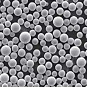
| Morphology | Spherical | Creates good powder flow and packing |
| Impurities | <100 ppm O2 | Maintains alloy mechanical properties |
| Apparent density | Up to 80% of material density | Indicates powder packing and spreading |
| Flow rate | Hall flowmeter >15s/50g | Ensure smooth powder spreading during printing |
Precise particle size distributions between around 15-45 microns are required for high resolution printing, good surface finish, and adequate flow properties. Spherical powder morphologies allow smooth feeding and spreading of the powder across the bed.
Chemical purity is critical to achieve intended as-printed material performance. Any oxidation or contamination can reduce strength and ductility.
Flow rates are tested according to ASTM B213 standard using a Hall flowmeter funnel. Good apparent powder density above around 4 g/cc is needed for consistent powder layers.
Gas and water atomization are common techniques to produce spherical metallic powders meeting requirements for additive manufacturing. Powders are sieved to ensure uniform particle sizes.
Choosing a Metal Powder Bed 3D Printing Service
Selecting the right metal AM service provider is key to getting high quality printed parts. Here are factors to consider:
How to Evaluate and Select a Metal 3D Printing Service
- Experience – Look for years of experience specifically with metal AM to evaluate expertise
- Materials – Ensure provider offers required metals like titanium, tool steel, precious metals
- Part size – Choose service with build volume to suit required part dimensions
- Quality processes – Should follow rigorous quality control protocols at all stages
- Post-processing – See if provider can offer secondary finishing like CNC machining
- Applications expertise – Important for highly regulated sectors like aerospace, medical
- Certifications – Look for ISO and industry specific certifications for processes
- Customer service – Responsive technical support team critical for design, application advice
- Delivery times – Understand typical lead times and options for rush orders
- Pricing – Factor in material and geometry complexity, post-processing, volume
- NDA/IP protection – Your proprietary design data should be protected contractually
Design Guidelines for Metal AM Parts
To fully utilize the benefits of metal additive manufacturing, designs should follow DfAM (Design for Additive Manufacturing) principles:
Key Metal AM Design Guidelines:
- Optimize for weight reduction with lattice structures
- Consolidate assemblies into single complex parts
- Design internal features like conformal cooling channels
- Use organic, freeform shapes not possible with machining
- Minimize overhangs and design angled supports
- Orient to reduce part height and avoid large flat areas
- Design threaded holes to avoid support removal issues
- Allow extra thickness on thin walls prone to porosity
- Compensate for anisotropic material properties in different directions
- Design controlled porosity into surfaces when beneficial
Complex lattice structures with thinner members can reduce weight while retaining strength when 3D printed. Consolidating assemblies into single parts is a major advantage over conventional manufacturing.
Cooling channels and other useful internal voids no longer need to be drilled and can follow optimal organic paths. Overhangs prone to sagging can be avoided through angled lattices or sloped designs.
Parts orientation should aim to minimize Z height during printing to reduce residual stresses. Thin walls prone to porosity may need extra thickness to hit target material densities.
Cost Modeling and Economics of Metal AM
Determining whether metal additive is economically viable depends on assessing all costs:
Cost Factors for Metal Powder Bed AM:
- Machine depreciation – Spread high printer costs over lifetime
- Material costs – Powder metals can range from $100-$500/kg
- Labor – Operator labor, design, post-processing
- Energy consumption – High power lasers and other systems require significant electricity
- Production speed – Print volume per hour based on parameters, machine limits
- Post-processing – Machining, finishing steps add downtime and costs
- Facility costs – Required powder handling systems, inert gas, space
- Quality control – Testing parts during production and process qualification
- Safety and compliance – For regulated applications, documentation is extensive
The high cost of metal printers means evaluating lifetime machine usage for optimal utilization through higher production volumes. Material costs are also significant, especially for exotic alloys.
All labor must be accounted for – operators, engineers, designers, quality technicians. Energy consumption is high. Post-processing downtime reduces production speeds.
For aerospace and medical applications, compliance costs like documentation and quality systems are extensive. Careful cost modeling determines when metal AM is cost-effective.
Trends and Future of Metal Additive Manufacturing
Metal powder bed fusion is seeing rapid ongoing development and adoption:
Future Trends for Metal Powder Bed 3D Printing:
- Larger build volumes – Enclosures over 500mm cubed in development
- Faster build speeds – Improved scanning strategies and multi-laser systems
- New material options – More alloys like Aluminum F357 and M300 maraging steel
- Hybrid manufacturing – Combined printing, milling, inspection in single system
- Automated powder handling – Closed-loop recycling systems for powder management
- New applications – Expanding into oil and gas, electronics sectors
- Declining system costs – Industrialization will reduce printer costs over time
- Improved material properties – Through process refinements and HIP densification
- Expanded metallurgy – Improved characterization of microstructures and properties
- Industry standards – For processes and material quality in aerospace and medical
Larger build volumes will allow more complex and higher volume production. Multi-laser optic systems can dramatically increase building speeds.
Closed-loop powder handling systems will automate recycling and reuse while improving quality and safety. New exotic alloy options are being introduced yearly. Hybrid manufacturing combines additive and subtractive processes for complete in-situ machining.
Declining costs as the technology matures will continue expanding the applications. Further material research and benchmarking will expand the processed alloys and improve material performance. Extensive work on industry standards aims to accelerate adoption in aerospace, medical, and automotive sectors.
Conclusion
This guide covers the key aspects of metal powder bed fusion 3D printing, from the printing process and materials to applications, benefits, limitations and trends.
Additive manufacturing with metals is enabling disruptive innovations across industries thanks to its unique capabilities. The technology empowers weight reduction, part consolidation, design freedom, rapid prototyping, and customized metal parts production.
Despite limitations around printer costs, build size constraints, post-processing, and materials options, metal AM adoption is accelerating for an expanding range of mission-critical applications in aerospace, medical, automotive, and industrial sectors.
Ongoing process refinements, new materials, larger build volumes, hybrid systems, automated powder handling, and declining costs will drive expanded use of metal 3D printing for end-use production parts. This guide covers the current state and trajectory of this transformative manufacturing technology.
Frequently Asked Questions About Metal Powder 3D Printing
Here are answers to some common questions about metal powder bed fusion additive manufacturing:
Q: What materials can be 3D printed using metal powder bed fusion?
A: Common alloys include titanium, aluminum, nickel, stainless steel, tool steel, cobalt-chrome, precious metals like gold and silver, and copper. New alloys are constantly in development.
Q: What industries use metal AM today?
A: Aerospace, medical, dental, automotive, oil and gas, industrial machinery, and jewelry are leading adopters of metal AM. The technology is ideal for complex, low volume parts.
Q: How accurate is metal powder bed 3D printing?
A: Dimensional accuracy can reach up to ±0.1-0.2% with finer resolutions around ±50μm possible based on parameters and post-processing.
Q: Does metal AM require any special facilities?
A: It requires an inert gas atmosphere during printing, usually argon. Powder handling systems with venting and sieving are also recommended. No other special facilities are required.
Q: What factors affect the surface finish?
A: Layer height, laser parameters, powder size distribution, and post-processing like polishing all affect surface finish. Ra values under 10 μm are possible.
Q: What determines the mechanical properties?
A: Alloy composition, powder quality and morphology, process parameters, heat treatments, and HIP all affect the final printed metal part properties.
Q: How expensive is metal powder bed printing?
A: Printer systems range from $100,000 to over $1,000,000. Material costs vary by alloy from $100-$500/kg typically. Operating costs are also high.
Q: How long does printing take for a medium sized part?
A: Build rates are typically 5-20 cm3/hour depending on part geometry, material, parameters, and printer model. A shoebox sized part may take 5-15 hours.
Q: What size parts can a metal printer make?
A: Current maximum build volumes are around 500 x 500 x 500 mm, but larger systems are in development. Larger parts can be segmented into multiples.
Q: What post-processing is required after metal AM?
A: Support removal, stress relieving, machining, drilling, surface finishing, heat treatments, and sometimes hot isostatic pressing.
Share On
MET3DP Technology Co., LTD is a leading provider of additive manufacturing solutions headquartered in Qingdao, China. Our company specializes in 3D printing equipment and high-performance metal powders for industrial applications.
Inquiry to get best price and customized Solution for your business!
Related Articles
About Met3DP
Recent Update
Our Product
CONTACT US
Any questions? Send us message now! We’ll serve your request with a whole team after receiving your message.

Metal Powders for 3D Printing and Additive Manufacturing
COMPANY
PRODUCT
cONTACT INFO
- Qingdao City, Shandong, China
- [email protected]
- [email protected]
- +86 19116340731


