Understanding the BJT Process
Table of Contents
Overview of the BJT Process
The Bipolar Junction Transistor (BJT) process is a fundamental concept in the field of semiconductor electronics. BJTs are essential components in many electronic devices due to their ability to amplify current. This guide provides an in-depth exploration of the BJT process, covering its types, properties, applications, advantages, and disadvantages. Additionally, we’ll dive into specific metal powder models used in BJT manufacturing, providing a thorough comparison to help you make informed decisions.
Types of BJTs and Their Properties
NPN and PNP BJTs
BJTs come in two main types: NPN and PNP. Both types operate using the same principles but differ in their configuration and charge carrier movement.
| Type | Configuration | Charge Carriers | Symbol |
|---|---|---|---|
| NPN | Emitter (N) – Base (P) – Collector (N) | Electrons | NPN Symbol |
| PNP | Emitter (P) – Base (N) – Collector (P) | Holes | PNP Symbol |
Composition and Characteristics of BJT Materials
The materials used in BJTs are crucial for their performance. Silicon (Si) and Germanium (Ge) are the primary semiconductors used.
Material Composition and Characteristics
| Material | Composition | Properties | Applications |
|---|---|---|---|
| Silicon (Si) | Pure silicon with doping elements like Phosphorus (N-type) or Boron (P-type) | High thermal stability, Low leakage current | General-purpose transistors, Power devices |
| Germanium (Ge) | Pure germanium with similar doping elements | Higher electron mobility, Lower thermal stability | High-frequency applications, Low-voltage devices |
Applications of the Symbol
BJTs are versatile components used in a wide range of applications. Below is a table outlining some key uses.
Applications and Uses of BJTs
| Application | Description | Examples |
|---|---|---|
| Amplification | BJTs amplify current, making them essential in audio and radio frequency devices. | Audio amplifiers, RF amplifiers |
| Switching | Used to turn electronic signals on and off in circuits. | Digital circuits, Microprocessors |
| Oscillation | BJTs are integral in creating oscillating circuits. | Signal generators, Oscilloscopes |
| Regulation | Used in voltage regulation circuits to maintain constant voltage levels. | Power supplies, Voltage regulators |
Specifications, Sizes, Grades, and Standards
BJTs come in various specifications to suit different applications. Understanding these specifications can help you choose the right BJT for your needs.
Specifications and Standards
| Specification | Description | Example Grades |
|---|---|---|
| Voltage Rating | Maximum voltage the transistor can handle. | 30V, 60V, 100V |
| Current Rating | Maximum current the transistor can conduct. | 100mA, 1A, 10A |
| Power Dissipation | Maximum power the transistor can dissipate without damage. | 200mW, 500mW, 1W |
| Frequency Response | Maximum frequency at which the transistor can operate effectively. | 100MHz, 300MHz, 500MHz |
Suppliers and Pricing Details
Several suppliers provide high-quality BJTs. Pricing varies based on specifications, quantity, and supplier.
BJT Suppliers and Pricing
| Supplier | Product | Price Range (per unit) |
|---|---|---|
| Texas Instruments | General-purpose BJTs | $0.10 – $1.00 |
| ON Semiconductor | High-frequency BJTs | $0.20 – $2.00 |
| Fairchild Semiconductor | Power BJTs | $0.50 – $3.00 |
| NXP Semiconductors | Low-noise BJTs | $0.15 – $1.50 |
| Infineon Technologies | Switching BJTs | $0.25 – $2.50 |
Comparing Pros and Cons of BJTs
BJTs have various advantages and limitations that affect their suitability for different applications.
Advantages and Limitations of BJTs
| Aspect | Advantages | Disadvantages |
|---|---|---|
| Performance | High current gain, Fast switching | Higher power consumption compared to FETs |
| Cost | Generally lower cost | Potentially higher cost for high-performance models |
| Thermal Stability | Better thermal stability in Si BJTs | Poorer thermal stability in Ge BJTs |
| Frequency Response | High-frequency operation in Ge BJTs | Limited by parasitic capacitance |
Metal Powder Models in BJT Manufacturing
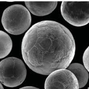
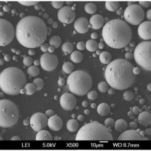
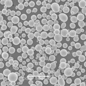
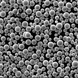
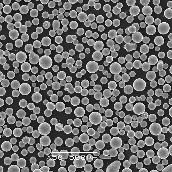
Various metal powder models are used in the manufacturing process of BJTs. These materials influence the efficiency and performance of the final product.
Specific Metal Powder Models
- Copper (Cu) Powder
- Description: Highly conductive metal powder used for improving electrical conductivity.
- Applications: Used in high-performance BJTs for power applications.
- Properties: Excellent thermal and electrical conductivity.
- Aluminum (Al) Powder
- Description: Lightweight and conductive, aluminum powder is used in certain BJT applications.
- Applications: Used in BJTs for lightweight and high-thermal conductivity needs.
- Properties: Good conductivity, lightweight.
- Nickel (Ni) Powder
- Description: Known for its corrosion resistance and stability.
- Applications: Used in environments where durability is crucial.
- Properties: High resistance to corrosion, stable performance.
- Iron (Fe) Powder
- Description: Commonly used due to its availability and magnetic properties.
- Applications: Used in BJTs that require magnetic properties.
- Properties: Magnetic, cost-effective.
- Silver (Ag) Powder
- Description: Offers the highest electrical conductivity among metals.
- Applications: Used in high-end BJTs for precision applications.
- Properties: Excellent electrical conductivity, expensive.
- Gold (Au) Powder
- Description: Extremely conductive and resistant to oxidation.
- Applications: Used in BJTs for critical and high-reliability applications.
- Properties: Excellent conductivity, highly resistant to corrosion, very expensive.
- Zinc (Zn) Powder
- Description: Provides good conductivity and is used in alloying.
- Applications: Used in BJTs for general-purpose applications.
- Properties: Good conductivity, affordable.
- Cobalt (Co) Powder
- Description: Known for its magnetic properties and high melting point.
- Applications: Used in specialized BJTs that require high-temperature stability.
- Properties: Magnetic, high melting point.
- Titanium (Ti) Powder
- Description: Lightweight and strong, used in high-strength applications.
- Applications: Used in BJTs where weight and strength are critical.
- Properties: High strength-to-weight ratio, corrosion-resistant.
- Palladium (Pd) Powder
- Description: Offers good conductivity and stability.
- Applications: Used in high-reliability BJTs.
- Properties: Good conductivity, stable, expensive.
FAQ
| Question | Answer |
|---|---|
| What is a BJT? | A Bipolar Junction Transistor (BJT) is a semiconductor device used to amplify or switch electrical signals. |
| What are the main types of BJTs? | The main types are NPN and PNP transistors. |
| What materials are used in BJTs? | Silicon (Si) and Germanium (Ge) are the primary materials used. |
| What are some common applications of BJTs? | They are used in amplification, switching, oscillation, and regulation. |
| How do NPN and PNP transistors differ? | NPN transistors use electrons as charge carriers, while PNP transistors use holes. |
| What are the advantages of using BJTs? | BJTs offer high current gain and fast switching. |
| What are the disadvantages of BJTs? | They tend to consume more power compared to Field-Effect Transistors (FETs). |
| What are the key properties of Silicon BJTs? | High thermal stability and low leakage current. |
| What metal powders are used in BJT manufacturing? | Copper, aluminum, nickel, iron, silver, gold, zinc, cobalt, titanium, and palladium powders are commonly used. |
| How do I choose the right BJT for my application? | Consider specifications like voltage rating, current rating, power dissipation, and frequency response. |
Share On
MET3DP Technology Co., LTD is a leading provider of additive manufacturing solutions headquartered in Qingdao, China. Our company specializes in 3D printing equipment and high-performance metal powders for industrial applications.
Inquiry to get best price and customized Solution for your business!
Related Articles
About Met3DP
Recent Update
Our Product
CONTACT US
Any questions? Send us message now! We’ll serve your request with a whole team after receiving your message.

Metal Powders for 3D Printing and Additive Manufacturing
COMPANY
PRODUCT
cONTACT INFO
- Qingdao City, Shandong, China
- [email protected]
- [email protected]
- +86 19116340731


