Inconel 3D Printed Parts
Table of Contents
Overview of inconel 3d printed part
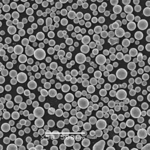
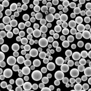
Inconel 3D printed parts refer to components fabricated from Inconel superalloy powders using additive manufacturing (AM) methods. Inconel grades offer exceptional heat and corrosion resistance combined with high strength, making them ideally suited to aerospace, power generation, and other demanding applications.
Key properties of Inconel 3D printed parts:
- High strength maintained to over 700°C
- Withstand aggressive environments including oxidation, corrosion
- Complex geometries produced directly from CAD models
- Reduced lead times and buy-to-fly ratios vs subtractive machining
- Choice of Inconel 625, 718 alloys and others to suit needs
- Requires hot isostatic pressing (HIP) to eliminate internal voids
Continue reading to learn more about popular Inconel alloys, mechanical properties, post-processing, uses and part qualification.
Alloy Types
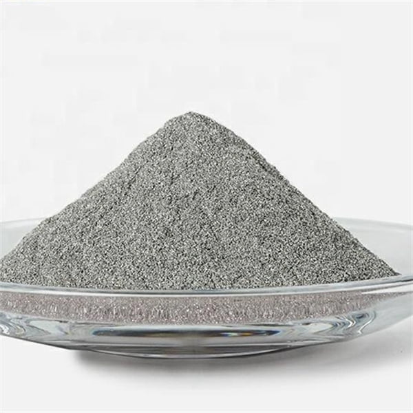
Common Inconel grades used in additive manufacturing include:
| Alloy | Nickel Content | Key Features |
|---|---|---|
| Inconel 625 | 60% min | Exceptional corrosion resistance, oxidation resistance to 980°C |
| Inconel 718 | 50-55% | Highest strength maintained to 700°C, age hardening response |
| Inconel 939 | N/A | High end service temperature from excellent coarsened grain structure stability |
Table 1: Popular Inconel superalloys available for AM processing
These alloys offer exceptional performance under heat and corrosion exposure better than stainless steels. Inconel 718 sees widest adoption today but new grades will expand capabilities further.
Properties of inconel 3d printed part
Key properties exhibited by Inconel 3D printed parts:
| Property | Description |
|---|---|
| High Temperature Strength | Strength maintained up to 700°C for age-hardened alloys |
| Thermal Resistance | Service temperatures over 1000°C possible |
| Corrosion Resistance | Excellent is variety of acidic, marine environments |
| Oxidation Resistance | Protective surface chromium oxide layer |
| Creep Resistance | Deformation resistance under loads at high temps |
| Hardness | Up to Rockwell C 40-45 when age hardened |
Table 2: Overview of mechanical and physical properties offered by Inconel AM alloys
The combination of strength, environmental resistance and stability under extreme temperatures makes Inconel an exceptionally versatile material system for critical applications.
Printed Part Accuracy
Dimensional accuracy and tolerances achievable with Inconel AM alloys:
| Parameter | Capability |
|---|---|
| Dimensional Accuracy | ±0.3% to ±0.5% as printed |
| Minimum Wall Thickness | 0.020 inches to 0.040 inches |
| Tolerances | ±0.005 inches common |
| Surface Finish | Up to Ra 3.5 μm (140 μin) finish as printed |
Table 3: Overview of printed accuracy and surface finish for Inconel AM parts
Post-processing like machining and finishing can further improve accuracy and surface finish. Data above is indicative – discuss specific requirements with candidate vendors for your application needs.
Part Testing of inconel 3d printed part
Qualifying Inconel AM components for end use requires standard testing protocols:
| Test | Purpose | Sample Methods |
|---|---|---|
| Chemical analysis | Verify alloy chemistry and microstructure | Optical emission spectrometry, image analysis |
| Tensile testing | Measure tensile and yield strengths | ASTM E8, ISO 6892 |
| Stress rupture testing | Determine rupture strength over time | ASTM E292 |
| Fracture toughness | Understand crack propagation resistance | ASTM E1820 |
| Corrosion testing | Evaluate material mass loss in environments | ASTM G31, ASTM G48 |
| Non-destructive testing | Detect surface/subsurface defects | Penetrant testing, CT scans |
Table 4: Common test methods for qualifying Inconel AM printed parts
Data must comply with applicable industry specifications like AMS, ASME, AWS, etc. as dictated by the end application and operating environment. Discuss needed validation testing with AM vendors.
Applications
Industries using Inconel 3D printed parts for demanding environments:
| Industry | Components | Benefits |
|---|---|---|
| Aerospace | Turbine blades, rocket nozzles | Maintains strength at high operating temps |
| Power Generation | Heat exchangers, valves | Corrosion resistance with high temp strength |
| Oil and Gas | Wellhead parts, fracturing components | Withstand harsh downhole conditions |
| Automotive | Turbocharger housings | Handles exhaust heat and gases |
| Chemical Processing | Reaction vessels, conduits | Resilience against corrosive reactions |
Table 5: Overview of Inconel AM parts usage across industries
Inconel alloys produce lightweight, high-performance components replacing conventionally fabricated hardware not capable of meeting application demands.
Post-Processing of inconel 3d printed part
Common secondary operations for Inconel AM printed parts:
| Process | Purpose | Method |
|---|---|---|
| Hot Isostatic Pressing | Eliminate internal voids and improve density | High pressure, high temp inert gas |
| Heat Treatment | Adjust microstructure and finalize properties | Solution annealing, aging profiles specific to alloy |
| Machining | Improve dimensional accuracy and surface finish | CNC milling/turning centers |
| Coatings | Enhance wear, corrosion and thermal resistance | Thermal spray, PVD, CVD coatings |
Table 6: Recommended post-processing techniques for Inconel AM printed parts
Nearly all parts will undergo HIP and heat treatment before use. Additional subsurface checks like penetrant testing or CT scans also inform certification. Discuss protocols tailored to your component with AM vendors.
Cost Analysis
| Parameter | Typical value |
|---|---|
| Inconel Powder Cost | $100-500 per kg |
| Buy-to-fly ratio | 1.5 : 1 |
| Lead Time | 4-8 weeks for printed parts |
| Printer Utilization | 50-75% |
| Finishing Allowance | 30% of printed part cost |
Table 7: Cost factors for Inconel AM part production
Significant powder reuse helps cost efficiency. Finishing steps like machining and coatings also add expense – budget 30% or more above printing costs depending on complexity.
Pros and Cons
Advantages
- Withstand much higher operating temps than stainless or titanium alloys
- Components maintain high strength across temperature range
- Unprecedented coolant channel geometries for enhanced heat transfer
- As-printed parts rival or exceed mechanical properties of cast Inconel
- Significantly lighter printed hardware than traditionally manufactured
- Buy-to-fly ratios near 100% with very little wasted powder
- Reduced lead times from on-demand digital inventories
Disadvantages
- Very high material costs starting around $100 per kg for powder
- Low system productivity around 5 kg powder used per day
- Significant parameter optimization required for new parts and alloys
- Extensive qualification testing mandated for aerospace and nuclear
- High operator skill level needed on specialized AM equipment
- Powder reuse up to only 10-20 cycles before refresh
- Porosity and residual stresses require HIP and finish machining
Frequently Asked Questions
Q: What size Inconel parts can be 3D printed?
A: State-of-the-art systems accommodate build volumes up to 1,000 mm diameter by 600 mm height. Larger components must be segmented into sub-assemblies. Multi-laser platforms continue expanding part sizes further.
Q: Does Inconel printing require special facilities or equipment?
A: Inconel generally prints in inert argon gas chambers rather than with filters or vacuum systems. Otherwise standard metal AM machines apply without exotic additions. Handling fine powders dictates care without specific room requirements.
Q: What lead time can be expected for Inconel AM part orders?
A: Typical quoted lead times fall around 4-10 weeks depending on part size, post-processing and testing selected. Digital inventories mitigate delays so printed components ship faster than castings with supply shortages.
Q: What industries offer the best Inconel AM business opportunities?
A: Aerospace, space, petrochemical and nuclear sectors push adoption of performance alloys like Inconel. Medical also offers growth designing certified implants. Standard stainless and tool steel parts now commoditized so more exotic alloys gain interest.
Q: Does AM enable any novel Inconel applications not possible previously?
A: AM facilitates formerly impossible conformal cooling channels and hollow internal structures to enhance heat transfer in tight spaces. Parts also see use atop rockets and satellites where weights were traditionally prohibitive or machining inaccessible. Continued R&D expands future capabilities further still.
Share On
MET3DP Technology Co., LTD is a leading provider of additive manufacturing solutions headquartered in Qingdao, China. Our company specializes in 3D printing equipment and high-performance metal powders for industrial applications.
Inquiry to get best price and customized Solution for your business!
Related Articles
About Met3DP
Recent Update
Our Product
CONTACT US
Any questions? Send us message now! We’ll serve your request with a whole team after receiving your message.

Metal Powders for 3D Printing and Additive Manufacturing
COMPANY
PRODUCT
cONTACT INFO
- Qingdao City, Shandong, China
- [email protected]
- [email protected]
- +86 19116340731


