MIM Manufacturing: A Complete Guide
Table of Contents
Overview of MIM Manufacturing
Metal injection molding (MIM) is a powder metallurgy manufacturing process used to produce small, complex metal parts at high volumes.
The key steps in MIM include:
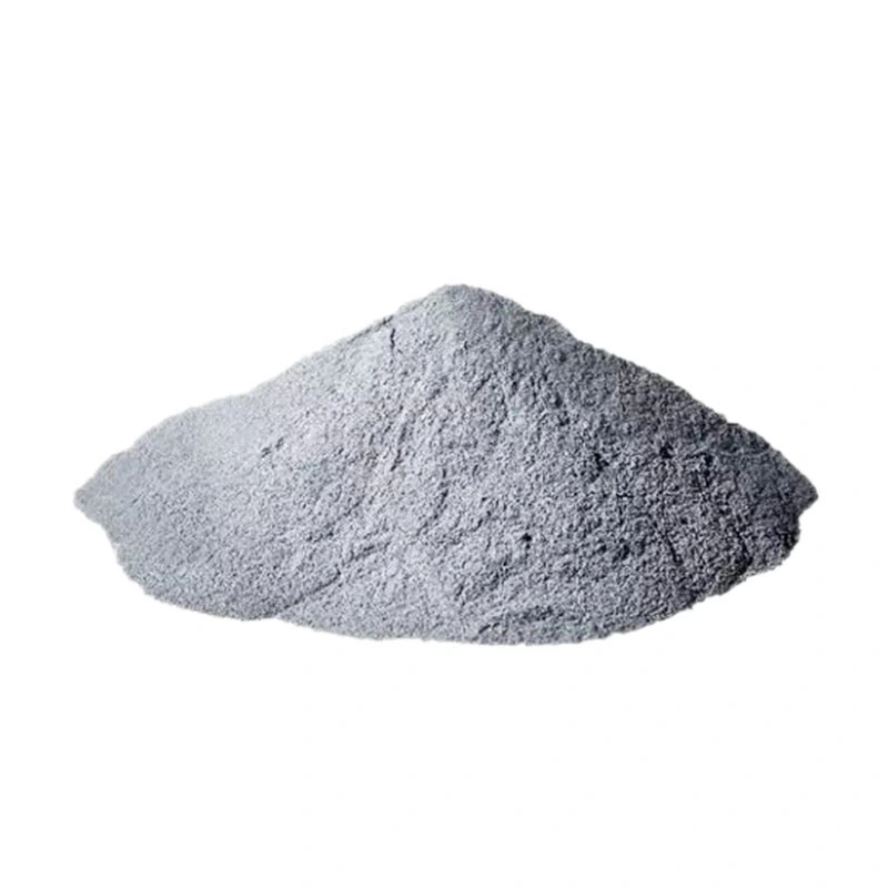
- Mixing fine metallic powder with binder to create a feedstock
- Injecting the feedstock into a mold using plastic injection molding
- Debinding to remove the binder leaving only the metal powder
- Sintering to densify the powder into a solid metal component
MIM combines the design flexibility of plastic injection molding with the strength and performance of machined metals. It is a cost-effective process for complex, high volume production of small parts.
How MIM Manufacturing Works
The MIM manufacturing process involves:
- Formulating a feedstock by mixing and pelletizing fine metal powder with polymer binders
- Heating the feedstock and injection molding it into the desired shape
- Chemically removing the binder through solvent or thermal debinding
- Sintering the debound metal component in a furnace to produce a fully dense part
- Optional secondary finishing operations like machining, drilling, plating
MIM allows the economical production of components with complex geometries, tight tolerances and excellent mechanical properties.

Types of Metals Used in MIM
A wide range of metals can be processed with MIM technology:
- Stainless steels – 316L, 17-4PH, 410, 420
- Tool steels – H13, P20, A2, D2
- Magnetic alloys – Soft and hard ferrites
- Copper alloys – Brass, bronze
- Low alloy steels – 4100, 4600
- Superalloys – Inconel 625, 718
- Tungsten heavy alloys
- Titanium alloys – Ti6Al4V, Ti6Al4V ELI
MIM is generally suited for any material that can be sintered to high density. Metals with melting points below 1000°C are preferred.
MIM Manufacturing Process Parameters
Critical process parameters in MIM include:
Feedstock development:
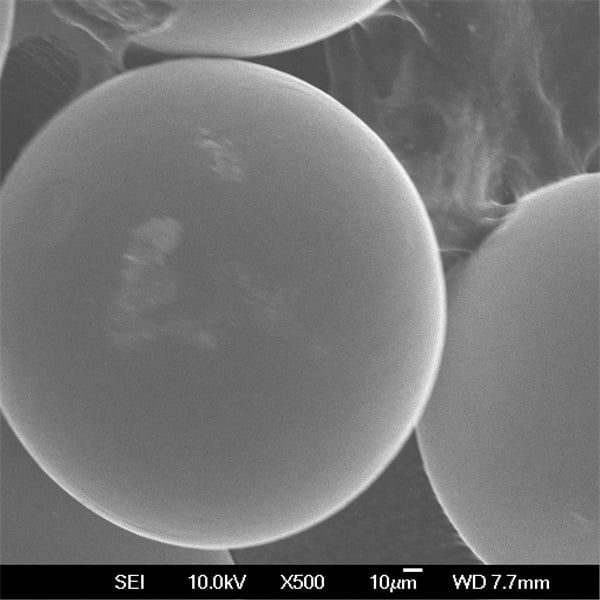
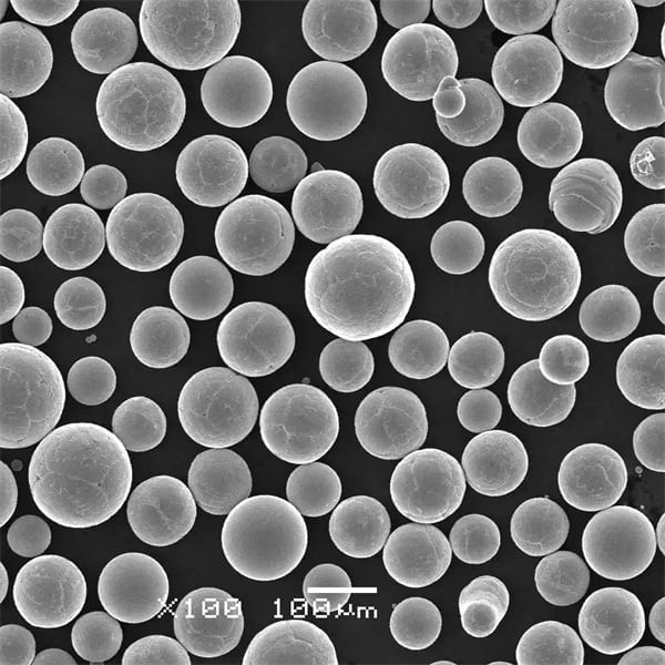
- Powder morphology, size distribution
- Binder composition
- Powder loading – typically 60-65 vol%
- Mixing process – temperature, time, atmosphere
Molding:
- Mold material – P20 tool steel preferred
- Injection temperature, pressure, speed
- Gate design
- Cooling system design
Debinding:
- Solvent, thermal, or catalytic debinding
- Debinding temperature, time, atmosphere
Sintering:
- Temperature profile – debinding, sintering steps
- Heating rate, sintering time, atmosphere
- Sintering temperature and pressure
MIM Design and Part Considerations
The MIM process enables design freedom, but some guidelines must be followed:
- Wall thickness: 0.3 – 4 mm range possible
- Surface finish: As-sintered is around Ra 1.5 μm
- Dimensional tolerances: ±0.5% is standard but ±0.1% achievable
- Avoiding trapped powder: No fully enclosed internal cavities
- Draft angles: > 1° draft angle preferred
- Sintering shrinkage: Approx 20% volumetric shrinkage
- Reducing defects: Generous corner radii minimizes cracks
Advanced simulation tools allow virtual optimization of the MIM process during design to reduce trial and error.
Benefits of MIM Manufacturing
Key advantages of utilizing MIM include:
- Complex geometries and tight tolerances
- Excellent mechanical properties
- Wide range of material options
- High production quantities at low cost
- Minimizes waste – near net shape process
- Reduced machining and finishing
- Component integration and part consolidation
- Automated process suitable for lights-out operation
- Environmentally friendlier than machining
- Scalable from prototypes to full production
The benefits make MIM suitable for cost-effectively manufacturing precision metal components at high volumes across industries.
Limitations and Challenges of MIM
Some limitations associated with MIM:
- Limited size – typically <45 g finished mass per part
- Restricted to metals capable of sintering to high density
- Extensive expertise required in feedstock formulation
- Upfront costs for mold and process development
- Straight sections and sharp corners prone to cracking
- Longer lead time compared to other processes
- Post processing often required to achieve final properties
- Lack of design freedom in some features like threads
- Secondary machining can be challenging on sintered metals
With proper feedstock and process design tailored for the application, these challenges can be overcome to utilize the full potential of MIM technology.
Applications of MIM Manufactured Parts
MIM finds widespread use across the following sectors:
Automotive: Lock hardware, sensors, fuel system and engine components
Aerospace: Impellers, nozzles, valves, fasteners
Medical: Dental implants, scalpel handles, orthopedic instruments
Firearms: Triggers, magazines, slides, hammers
Watches: Cases, bracelet links, clasps and buckles
Electrical: Connectors and leadframes for reliability
Typical part sizes range from 0.1 grams to 110 grams with the largest commercial production volumes in connectors, fasteners, surgical instruments, and orthodontic braces.
Cost Analysis of MIM Manufacturing
MIM manufacturing costs include:
- Feedstock development – Formulation, mixing, characterization
- Mold fabrication – High precision mold machining
- MIM machine – Large capital equipment investment
- Operation – Labor, utilities, consumables
- Secondary operations – Debinding, sintering, finishing
- Material utilization – Metal powder accounts for about 60% of total cost
- Consumable tooling – Multiple mold cavities to enable high volume
- Production volume – Setup costs amortized over total volume
- Buy-to-fly ratio – Only 2-4x compared to other PM processes
- Design optimization – Simple geometries with minimal machining
For large production volumes, MIM delivers very favorable cost at high manufacturing rates with excellent material utilization and near net-shape capabilities.

Selecting a MIM Manufacturing Partner
Key factors when selecting a MIM supplier:
- Demonstrated expertise and years of experience with MIM
- Material portfolio – range of stainless steel, tool steel, superalloy options
- Quality certifications – ISO 9001, ISO 13485 preferably
- Secondary processing capabilities – machining, heat treatment, surface finishing
- Stringent process and product quality control procedures
- R&D capabilities for feedstock formulation and process development
- Mold flow simulation and other design analysis expertise
- Program management skills to support customer projects
- Scalable capacity able to grow with production needs
- Competitive pricing with multi-year agreements
- Location enabling close collaboration and IP protection
Selecting an established MIM producer with niche focus on MIM will provide the best results as opposed to a general CNC metal machining shop.
Pros and Cons of MIM vs CNC Machining
Advantages of MIM:
- Excellent dimensional accuracy and repeatability
- Complex geometries unattainable through machining
- Near net shape with minimal material waste
- Scales efficiently to very high production volumes
- Automated process enables 24/7 operation
- Shorter lead times once setup
- Significantly lower part costs at high volumes
- Properties match or exceed machined metals
Disadvantages of MIM:
- High initial setup costs for feedstock and mold
- Limited size capabilities
- Restricted design freedom in some features
- Lower initial production quantities inefficient
- Extensive expertise required in feedstock formulation
- Secondary finishing operations may still be needed
- Longer lead times and lower quality for initial prototypes
For small complex metal parts produced in very high volumes, MIM becomes the most time and cost efficient manufacturing method.
Comparison Between MIM and Metal 3D Printing
MIM vs 3D printing main differences:
| Parameter | MIM | 3D Printing |
|---|---|---|
| Process | Binder injection molding + sintering | Powder bed fusion or binding |
| Materials | Wide range of alloys | Limited material options |
| Part size | < 45 grams | Up to several kg |
| Accuracy | Excellent, ±0.5% | Moderate, ±1% |
| Surface finish | Very good | Medium to poor |
| Production scale | 10,000s to millions | Prototyping to medium volumes |
| Cost per part | Very low | Medium to high |
| Secondary finishing | May be required | Usually required |
| Lead time | Longer for process development | Faster prototypes but slower serial production |

FAQ
What is the typical tolerance capability for MIM manufacturing?
MIM can reliably achieve dimensional tolerances of ±0.5% with advanced processes capable of ±0.1% tolerance for small precision components.
What are common MIM feedstock compositions?
Typical MIM feedstocks consist of 60-65% metal powder loading with 35-40% binder comprising polymers like polypropylene, polyethylene, and polystyrene. Waxes help improve powder flow.
Can MIM manufacture parts in multiple materials?
Yes, MIM can produce composite and graded structures by injection molding different feedstocks into each mold cavity or using binders with different melting points.
What molded part size can be achieved with MIM?
MIM moldings are typically restricted to parts smaller than 45 grams in mass and dimensions less than 50 mm. Larger or heavier components become difficult to sufficiently fill and densify.
How does MIM compare to die casting for small metal components?
MIM provides higher dimensional accuracy and material strength but die casting has faster cycle times. MIM is more suitable for complex geometries while die casting is preferable for simpler forms.
Share On
MET3DP Technology Co., LTD is a leading provider of additive manufacturing solutions headquartered in Qingdao, China. Our company specializes in 3D printing equipment and high-performance metal powders for industrial applications.
Inquiry to get best price and customized Solution for your business!
Related Articles
About Met3DP
Recent Update
Our Product
CONTACT US
Any questions? Send us message now! We’ll serve your request with a whole team after receiving your message.

Metal Powders for 3D Printing and Additive Manufacturing
COMPANY
PRODUCT
cONTACT INFO
- Qingdao City, Shandong, China
- [email protected]
- [email protected]
- +86 19116340731


